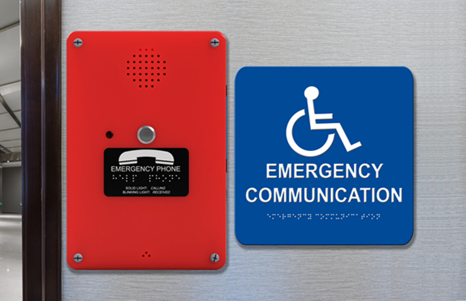

Command Center Call Boxes (2400 Series)
- The Command Center call boxes, designed for large-scale installations of up to 116 call boxes, provide a reliable means for distressed individuals to communicate with rescue personnel during an emergency
- Utilizing a single pair of wires for each call box, the system ensures an efficient and cost-effective installation process
- The Command Center call boxes offer a scalable and robust solution without compromising on quality or compliance, ensuring top-tier reliability and adherence to industry standards
Power Requirements: Designed to be powered from the Distribution Module and requires a single pair from the Distribution Module Programming Features:
- Programmable with up to 2 emergency numbers
- On-site programming
- Recordable location message (25 seconds)
- On-site programming capability with numeric programming
Phone Capabilities:
- Recordable location message (25 seconds)
- Automatic dialer (31 digit programmable memory)
- Automatic answer feature with audible ring
Supervision: Can be obtained with addition of Supervisory Module (2500_SPRVSR) Additional Optional Features:
- NEMA 4 exterior rated
- Mushroom button
Warranty: 2 years
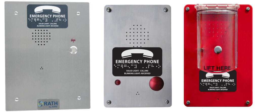
Command Center Call Boxes available in 3 mounting options:
Flush Mount
 2400-808NSP Flush Mount Face Plate: 9-1/2″ H x 7-1/2″ W Back Box: 8″ H x 6″ W x 3″ D Style: Brushed Stainless Steel |  2400-808NMP Flush Mount Face Plate: 9-1/2″ H x 7-1/2″ W Back Box: 8″ H x 6″ W x 3″ D Style: Antique Bronze | 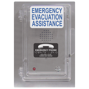 2400-808SSPC2 Flush Mount with Cover Face Plate: 11-3/8″ H x 8″ W Back Box: 9-7/8″ H x 6-1/2″ W x 3″ D Cover: 9-3/4″ H x 6-1/2″ W x 1-1/4″” D Style: Brushed Stainless Steel |
Surface Mount
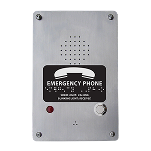 2400-805SP Surface Mount 7-1/4″ H x 4-3/4″ W x 1-7/8″ D Style: Stainless Steel Box | 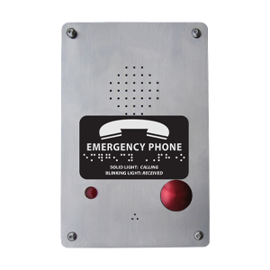 2400-805SPM Surface Mount 7-1/4″ H x 4-3/4″ W x 1-7/8″ D Style: Stainless Steel Box | 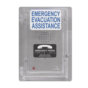 2400-805SSPC2 Surface Mount and Cover Face Plate: 10″ H x 6-17/25″ W Back Box: 9-7/8″ H x 6-1/2″ W x 3″ D Cover: 9-3/4” H x 6-1/2” W x 1-1/4” D | 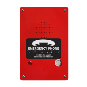 2400-805RP Surface Mount 7-1/4″ H x 4-3/4″ W x 1-7/8″ D Style: Red Powder Coated |
Exterior Rated
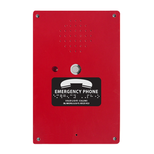 2400-805LP Surface Mount 9-7/8″ H x 6-5/8″ W x 3-1/4″ D Style: Red Fiberglass, NEMA, Exterior Rated | 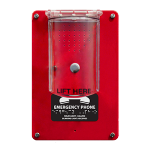 2400-805LPC1 Surface Mount with Cover Call Box Size: 9-7/8″ H x 6-5/8″ W x 3-1/4″ D Cover Size: 6-2/5″ H x 3-3/4″ W x 2-1/4″ D Style: Red Fiberglass, NEMA, Exterior Rated |
Files and Resources
Specifiers' Corner
The Specifiers’ Corner is designed to provide Architects, Engineers, Contractors, Fire Marshals, Building Code Officials, Inspectors, AHJs, and end users with the essential information that may be needed for a project: Submittal Documents, Manuals/Wiring Diagrams, Data Sheets,CAD and Code Requirements
Contact info
You also can contact us through our phone number, our email address, and we’ll get back to you
We believe that ongoing education is paramount to your professional development.
As the code and training experts, our website offers all the documentation and educational resources needed to assist you in making the right decisions.
